The history of the Tiger heavy tank is often presented as a duel between two models: The Tiger H1 designed by Henschel with a mechanical transmission and Tiger (P) designed by Porsche with an electric transmission that allegedly led to its downfall. This common presentation is incorrect. The Germans worked on three Tiger tanks in the spring of 1942: the Tiger H1, Tiger (P) Typ 101 with a Siemens electric transmission, and the Tiger (P) Typ 102 with a Voith hydromechanical transmission. A lot has been written about the first two, but the last remained in the shadow for a long time. Books only contained scattered mentions or dry overviews of this tank without any photographs or blueprints.
 |
| Typ 102 refuelling in the vicinity of the Nibelungenwerke factory. The small fuel tanks and poor fuel economy meant this had to happen quite often. Ferdinand Porsche, director of Steyr Oscar Hacker, and Voith chief engineer Fritz Kugel. |
The author of this article first wrote an article about the Tiger (P) Typ 102 back in 2017, describing its design, production, and trials. However, it contained many serious mistakes and left a lot of mysteries. Michael Fröhlich's book Der andere Tiger (The Other Tiger) was published in 2019. The author performed a lot of work and found a lot of new information on the Tiger (P) Typ 102, but not without mistakes. Now, combining all known information, the author returns to the topic with the first complete history of this mysterious Tiger.A different way
The CIOS report on the work of Porsche KG mentions the fact that Porsche's engineers doubted the suitability of mechanical transmissions for heavy tanks and thus began experiments with electric and hydromechanical transmissions. However, many versions of this story omit the mention of hydromechanical transmissions altogether, describing the electric ones as complex, unreliable, and expensive. As a result, Ferdinand Porsche is painted as a man who constantly tried to fit electric transmissions everywhere he could, ignoring his failures and with no regard for practicality. Allegedly, his competitors in the Ordnance Directorate and at Henschel didn't have their head in the clouds and used much more practical mechanical transmissions.
Let's start from the last assertion. In a simple mechanical transmission, the revolutions and torque change in quantized steps, according to the selected gear. A tank can drive in different conditions, from good paved roads to liquid mud, an endless spectrum of scenarios each with their own optimal torque, but with a limited number of gears. In other words, a conventional gearbox does not allow the tank to rationally use the power of its engine. There are also other drawbacks. The driver has to often change gears and depress the clutch, which takes a lot more effort than in a car. The engine stops powering the drive sprocket while the gear is changed, which makes changing gears in very difficult conditions quite hard. The engine is also mechanically linked to the drive sprocket, as a result of which it is subject to heavy loads and cannot always produce full power.
 |
| Maybach SRG 328 145 shaftless gearbox used on Pz.Kpfw.III Ausf.E-Ausf.G and VK 30.01 (H) tanks. The gears are selected via a combination of five levers, four of which have a vacuum actuator. When the gears are changed, the brake and synchronization accelerator are activated automatically. All of these operations take a fraction of a second and require precise manufacturing to work. |
The aforementioned problems could only be solved by complicating the design significantly. Department #6 of the Ordnance Directorate responsible for motorization of the Wehrmacht chose this option. Heinrich Kniepkamp developed a new mechanical transmission consisting of a semiautomatic shaftless gearbox and a double differential three-radius turning mechanism. His ideas were discussed in another article. Here, let us focus on the most important thing. Shaftless gearboxes give you the largest number of gears with the highest range of speeds. Double differential turning mechanisms make the tank more controllable and reduce losses in power. The semiautomatic mechanism makes driving simpler. However, the radically more complex transmission resulted in many problems. It would take 3-4 years before semiautomatic control systems were production ready. Without them shaftless gearboxes would not work. Transmission problems led to a delay in Henschel's work on heavy tanks. FOr instance, when working on the D.W. and VK 30.01 (H) the engineers had to replace the turning mechanism twice and account for two alternative gearboxes. One of the variants was a double differential transmission composed of the SMG 90 semiautomatic gearbox and L320C three radius turning mechanism. It resulted in a failure of Pz.Sfl.IVc trials in November-December of 1942. Keep in mind that the VK 30.01 (H) was essentially a 1939 tank! This is the complex situation that hides behind the claim that mechanical transmissions are more rational.
In the same conditions, Porsche KG chose a different direction: automatic continuous transmissions. The VK 30.01 (P) used two V-10 air cooled Typ 100 engines. They connected to two generators that in turn powered two electric motors that turned their respective drive sprockets. The electric motors automatically and gradually changed the torque within a wide range of speeds. If the resistance to driving increases, they automatically and without any input from the driver increase torque by reducing revolutions or vice versa. This process happens gradually and seamlessly, always keeping power on the drive sprockets, which is important in off-road driving. The electric transmission radically simplifies driving the tank and allows for more rational use of power, always providing the optimal torque and best possible speed for any conditions.
 |
| VK 30.01 (P) trials, 1942. This tank offered experience in using an electric transmission with an air cooled engine. |
The electric transmission had other advantages. It allows for the same speeds forward and in reverse. The engines lack a mechanical linkage to the drive sprockets and thus can work at optimal speeds, giving maximum power if necessary. For instance, when a captured Ferdinand was tested in the USSR it achieved a top speed of 35 kph on a highway. The engines were running at half power because that was sufficient. In an analogous situation, a mechanical gearbox would accelerate the engines to maximum RPM even though their full power was not needed. The system designed by Porsche KG also allowed driving at half speed if one engine was disabled.
Voith's alternative
Despite the aforementioned advantages, electric transmissions never became the standard in tank building. They had three serious drawbacks that could not be solved at the time. The first was that the electric drive was very heavy and took up a lot of space. Two generators, two electric motors, and the control system of the Tiger (P) weighed 4318 kg. To compare, the shaftless gearbox and double differential turning mechanism on the Tiger H1 weighed 1345 kg, almost three tons less. The large size meant that the internal volume of the tank had to be greater, which made it even heavier. Second, generators and electric motors were very expensive and used a lot of valuable copper. One Tiger (P) transmission used about 940 kg of it. To compare, an entire Tiger H1 needed 93 kg of copper. Third, the transformation of mechanical power to electric and back was inefficient, which resulted in low fuel economy.
 |
| Voith hydromechanical transmission for the Tiger (P) Typ 102. |
The heavy and expensive electric transmission has an alternative: the hydromechanical transmission. The torque converter automatically and gradually changes the torque and the oil buffer prevents a direct linkage between the engine and drive sprockets. This is a simple, light, and compact alternative to a generator and an electric motor. However, as torque increases so does the loss of power, and so the torque converter only works efficiently in a small range and cannot fully replace the gearbox. As a result, it is often used as a part of a hydromechanical transmission that also has a turning mechanism and a 2-4 speed gearbox. This transmission is a lot lighter and cheaper than an electric one, although the fuel economy is still worse compared to a mechanical gearbox due to increased loss of power.
The idea to use a hydromechanical transmission instead of an electric one came up during the design of the VK 30.01 (P). On December 17th, 1940, Ferdinand Porsche and Oscar Hacker first met with representatives of Voith, a company that produced turbines for torque converters. The engineers discussed a turning mechanism and conducted preliminary calculations for a transmission with two torque converters, each responsible for their own range of speeds (this will be explained later). The next meeting with Voith was held on March 14th, 1941. Since development of the VK 45.01 (P) began in July, the hydromechanical transmission for the VK 30.01 (P) was never produced.
 |
| Typ 102 hydromechanical transmission from the side of the torque converters. |
Unlike the VK 30.01 (P) the VK 45.01 (P) was planned in two variants from the start: the Typ 101 with a Siemens electric transmission and Typ 102 with a Voith hydromechanical transmission. The first discussion of the future Typ 102 began on July 12th, 1941, when work on the VK 45.01 (P) was just beginning. Voith was not only responsible for the design of the Typ 102 transmission, but also provided the cooling system fans, and so its representatives often met with engineers from Porsche KG. Blueprints of the hydromechanical transmission were prepared in January and February of 1942, and on March 23rd Krupp was informed that half of the first 100 VK 45.01 (P) built would have hydromechanical transmissions.
Design of the Typ 102
The Typ 101 with the electric transmission was the primary tank. A number of factors suggest this. The first is that the design of the hydromechanical transmission was finished not long before the first tank. The second is that the unusual layout of the VK 45.01 (P) with two engines in the center of the engine compartment was clearly chosen to house the generators and electric motors. Voith had a difficult job: fitting a hydromechanical transmission in the existing compartment so that the Typ 102 was as close to the electric model as possible and could be built in parallel. Let us see what they achieved.
 |
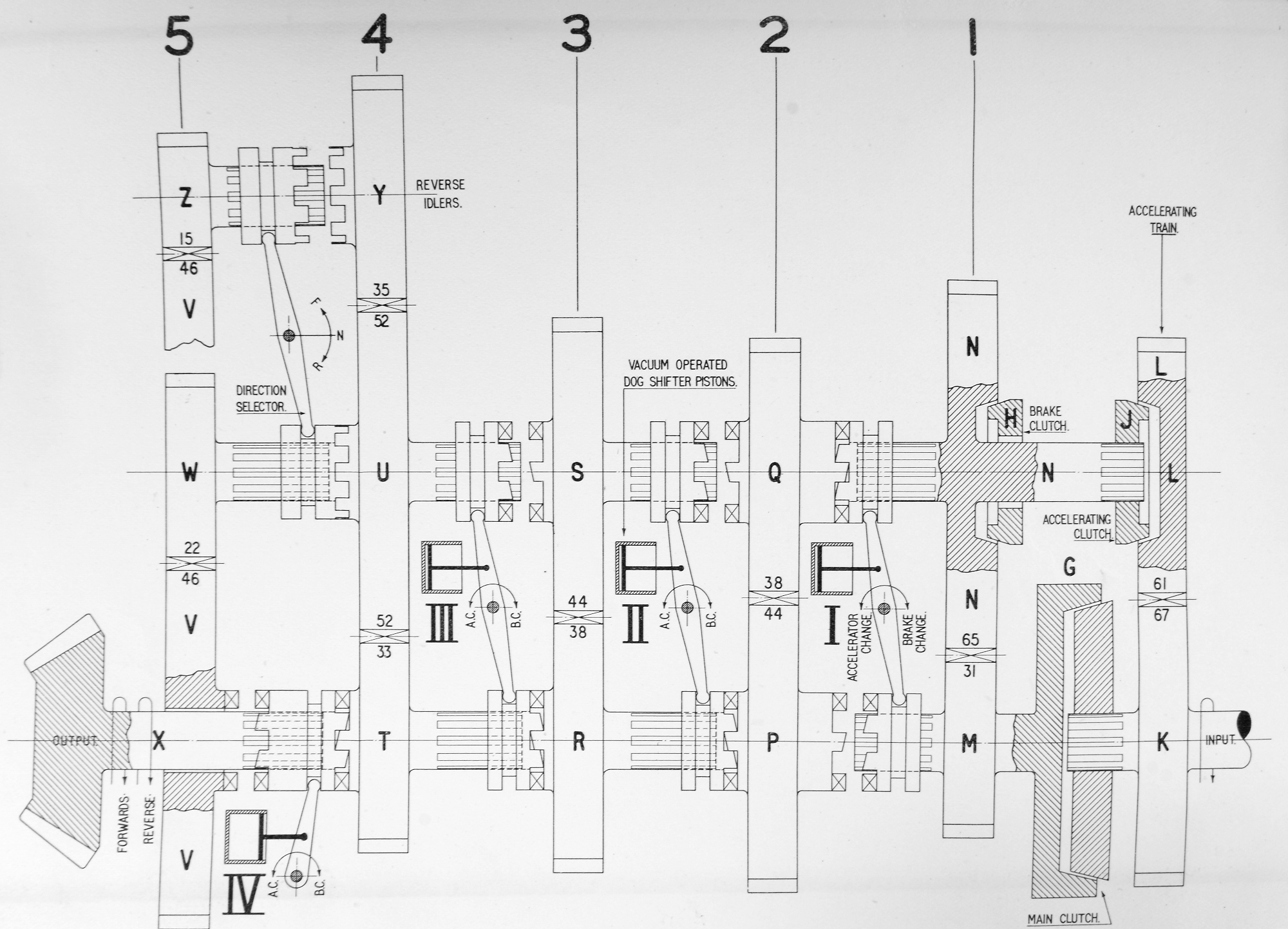
| Diagram of the Typ 102 hydromechanical transmission drawn by Vasily Chobitok. |
The Typ 102 transmission was separated into two parts. The torque converter block was located in front of the engines instead of the generators. The turning mechanism block was located behind the engine instead of the electric motors. They were joined together by a driveshaft that ran between the engines.
Each engine was connected to the drive shaft that drove the cooling fans and oil pumps. The control system compressor and generator were mounted on one side. Provisions for water pumps were also made, since at one point there was talk of VK 45.01 (P) variants with water cooling: Typ 130 and 131. The transmission that was built had those openings plugged. The driveshaft drove an intermediate shaft with two torque converters. Each torque converter had an output shaft driven though its own pair of gears. Finally, a crankshaft powered the turning mechanism. Since there were two engines, the transmission had four torque converters.
 |
| Torque converter block blueprint. The cooling fan drive can be seen in the top left. Photo via Harold Biondo. |
 |
| Hydraulic pumps that filled the torque converters. The water cooling pump can be seen on the upper left. The Tiger (P) had air cooled engines, so it was plugged. Photo via Harold Biondo. |
Voith's idea was as follows. In neutral, both torque converters were empty. In first gear, the first torque converter was filled with oil and began to spin its pair of gears with a ratio of 1.875. In second gear, the second torque converter was filled with oil. The power was supplied through a different pair of gears with a ratio of 0.674. The first torque converter was emptied. Gears were changed automatically, but the driver could manually set the desired gear or neutral. This unusual system was already in use by Voith on their locomotives. It allowed for gradual shifts between speeds without mechanical wear and was very easy on the driver, but the use of four torque converters due to having two engines made the system bulky.
Let us move on to the turning mechanism. The crankshaft rotated a planetary two-speed reduction gear with gearing ratios of 1 and 2.7. The lower gear was meant for especially difficult conditions such as off-roading, driving on only one engine, or towing another tank. This was a reserve gear and could only be engaged when the tank was stopped and in neutral. As a result, the reduction gear was not synchronized and there was no control linkage to the driver's station. The gears were picked in such a way that the second slow gear was identical to the first fast one, essentially giving the tank three gears with a range of 7.5.
 |
| Two-speed planetary reduction gear. Photo via Harold Biondo. |
There were two conical gears on the output shaft of the two-speed reductor gearing, a small one and a large one. The small one drove the oil pumps and the large one was linked to two conical gears on the turning mechanism shaft. A jaw coupling linked the two. Engaging the left or right gear activated the forward or reverse drive. The middle position was neutral. This is how the transmission provided the same speed in forward or reverse.
Each side of the two-stage turning mechanism consisted of a planetary gear train, brake, hydraulic retarder, and multi-disk clutch. The driving shaft of the turning mechanism was joined to the epicycloid, and the driven shaft to the pinion carrier. The sun gear was linked to the brakes and clutch. The design worked as follows. Both clutches were engaged during steady driving. The pinion carrier and sun gear rotate at the same speed. The gearing ratio is one. To turn right, the clutch on the right side is disengaged. The sun gear begins to turn freely, the track is unpowered, and slows down. If the lever is pulled further, oil is supplied to the right hydraulic retarder and it begins to brake the sun gear, reducing the speed of the track further.
 |
| Turning mechanism blueprint fragment. The quality of the archive document leaves much to be desired. From left to right, this image shows the clutch, drum brake, hydraulic retarder, planetary gear train, forward and reverse conical gears. |
Let us pull the lever even further. Now the right brake is activated and the sun gear is fully stopped. The gear ratio is 1.32 and the tank steadily turns at a radius of 11 meters. This is the first stage. Finally, in the last position of the lever the brake is released, the track is blocked fully, and the tank turns with a radius of 2.68 meters. This is the second stage. The presence of two stages improves controllability, reduces loss in power, and the hydraulic retarders can slow down the track for a long time as they have no mechanical wear and the waste heat dissipates in oil.
The control system is no less interesting. To make the driver's job easier, the track brakes and clutches were controlled with a hydropneumatic system. A compressor filled two tanks with air, from where it was supplied to pneumatic valves and air-hydraulic cylinders under the driver's seat. Each turning lever was linked to three valves. Pulling on a lever opened and close the valves, enabling and disabling their respective clutches and brakes.
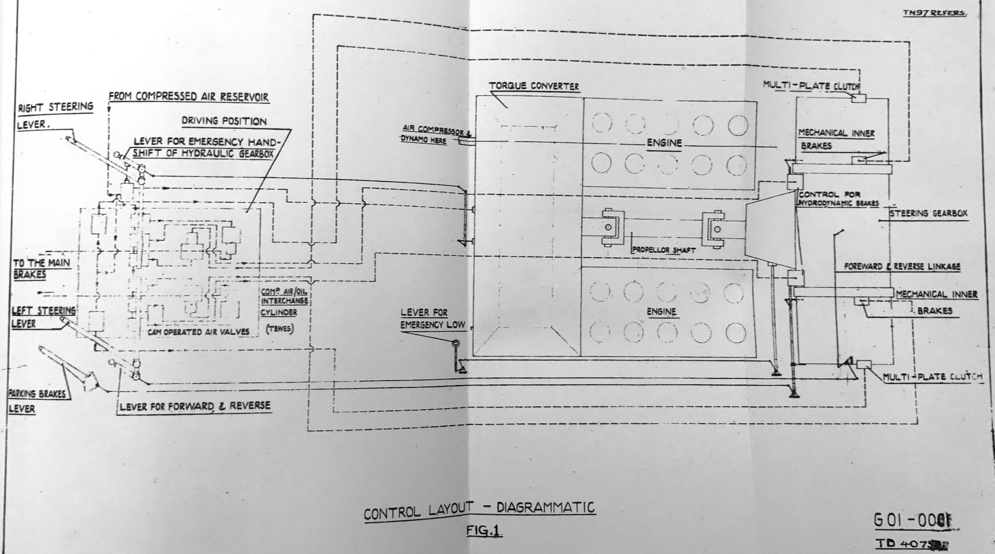 |
| Typ 102 control system. The pneumatic and hydraulic lines are shown in dotted arrows. Photo via Harold Biondo. |
Two of the valves actuated hydraulic brakes located in the idlers (this is why the idlers wheels had crowns). These brakes stopped the tracks during turning. The rear brakes were used as parking brakes and also blocked the sun gear to enable the large radius turn. This system was inherited from the electric Typ 101, which had parking brakes in the rear installed in one unit with the electric motors and used brakes in the idlers for turning. This allowed the whole hydropneumatic system to be compactly located in the front of the hull, reducing the length of the lines and thus giving a faster response time. The Typ 102 had to run its hydraulic and pneumatic control lines to the rear of the hull. As demonstrated later, this reduced the tank's controllability.
Production and trials
As mentioned above, the initial plans called for half of the first 100 Tiger (P) tanks to be built with a hydromechanical transmission. Production of 50 Typ 101 and 50 Typ 102 was discussed at a meeting in Stuttgart between Porsche, Krupp, and Ministries of Ordnance and Ammunition on March 23rd, 1942. These plans were soon revised. Voith made changes to their hydromechanical transmission, making it necessary to alter existing hulls.
On April 4th Nibelungenwerke informed Krupp that it cannot modify the Typ 102 hulls on its own since all equipment was being used for Typ 101 production. Nibelungenwerke had received 14 Typ 101 and the same number of Typ 102 hulls by that point. On April 18th, Porsche sent Krupp new blueprints of the Typ 102 engine and transmission compartment. Soon after Nibelungenwerke asked to not send Typ 102 hulls anymore since there was no room to store them.
 |
| Hitler inspects the Nibelungenwerke factory, June 20th, 1942. Due to a shortage of room the hulls are stacked on top of each other. |
The finished Typ 102 hulls needed such serious changes that not a single vehicle would be finished in time. It was easier to modify them to build Typ 101s with electric transmissions. On May 8th Porsche told Krupp to build only 10 tanks out of 100 with hydromechanical transmissions. Production of the 90 electric Typ 101 tanks was higher in priority. As a result, only one Tiger (P) was built with a hydromechanical transmission. Krupp and Nibelungenwerke converted the remaining 14 hulls to use electric transmissions.
The only Typ 102 prototype was used for trials with a dummy turret. Due to unreliable air cooled engines, the main problem of the Tiger (P), the trials proceeded with constant difficulties. The Typ 102 drove for 2000 km in the vicinity of Nibelungenwerke by March of 1944, at which point it was sent to Kummersdorf where it drove for another 200-300 km. Porsche and Voith considered the hydromechanical transmission as a whole to be a success. However, there were some growing pains. The pneumatic system disengaged the clutch with a noticeable delay, as a result of which the tank had a delay when turning at speeds over 25 kph. There were 2-3 cases during trials where the driver lost control of the tank and it ran off the road at nearly top speed. Second, there were issues with liners in the turning mechanism. A cowling was installed above the rear grate as a result of the oil squirting out. As information on the Typ 102 is very sparse, it is not known whether or not these issues were resolved during trials and what effect they had on subsequent production plans.
 |
| The cowling on the back shows that this is the Typ 102. Stains from leaking oil can be seen underneath. Ferdinand Porsche, Oscar Hacker, and Fritz Kugel stand on the dummy turret. Vicinity of Nibelungenwerke, December 23rd, 1943. |
The subsequent fate of the Typ 102 is not fully known. Famous researchers Thomas Jentz and Hilary Doyle mention only that one prototype was built and that post-war interrogations of Porsche and Voith staff lack any more information. Michael Fröhlich tried to put together a more complete picture, but his attempt was not successful. Fröhlich gives the Typ 102 serial number 150013, mixing the history of the 150013 tank with an electric transmission and the Typ 102 prototype. Tank 150013 took part in comparative trials in Bad Berka, then was sent to Kummersdorf in November of 1942, where it was used for Ferdinand towing trials. It was converted into a Panzerbefehlswagen VI P at Nibelungenwerke in early 1944 and sent to the 653rd Heavy Tank Destroyer Battalion. During conversion tank 150013 received additional front armour and Ferdinand style Maybach HL 120 TRM engines. This is the only Tiger (P) to have fought and subsequently be lost in battle.
 |
| The rear cowling and dummy turret suggest that this is the Typ 102. |
Fröhlich mentions that tank 150013 allegedly took part in the Ferdinand towing trials at Kummersdorf in late August of 1943, but in another place he writes that the Typ 102 chassis was sent to Kummersdorf only in March of 1944. This contradiction is never explained. It is also unclear how the tank can simultaneously be used for trials and undergo a conversion into a command tank. Fröhlich claims that the Tiger (P) was equipped with a hydromechanical transmission and air cooled engines. However, these engines had a very poor reputation and was not used anywhere else. Service of a tank with these engines would be very difficult. Using a tank with the Maybach HL 120 TRM with an electric drive to unify the tank with the Ferdinands is more reasonable. Finally, we know the weight of tank 150013 before conversion: 59,305 kg. This matches the weight of a Typ 101 with an electric transmission. The author estimates that the Typ 102 would have been about two tons lighter. Fröhlich's version of events is inconsistent and unlikely. Alas, we cannot fully reconstruct the story of the experimental Typ 102.
Evaluation
Voith engineers had the objective of creating a hydromechanical transmission that worked analogously to the electric one and could be used on the Tiger (P) with minimal changes. They succeeded at this. Like the electric transmission, the hydromechanical one automatically and seamlessly changed the torque, it was easy to use, allowed driving with just one engine, allowed for a top speed of 35 kph and a high reverse speed that was only limited by the running gear design.
Production of the Typ 102 used almost two tons less metal than the Typ 101. While the Typ 102 needed more aluminum, savings in copper ran up to almost 1400 kg per tank. It is not surprising that the hydromechanical transmission was much lighter. The author does not have information about the total weight, but it is known that the two generators weighed 1828 kg and the torque converter block just 800 kg. The electric transmission was also much more time consuming to produce: 3100 man hours compared to 1515 for one hydromechanical transmission. The Tiger (P) Typ 102 and Tiger H1 were equivalent in production complexity, while the Tiger (P) Typ 101 was much more complicated to produce.
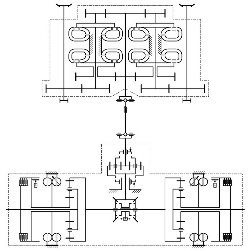
 |
| Further development of Voith's idea: a hydromechanical transmission for the Typ 250 tank. The gearbox and double differential are combined in one compact assembly. |
Porsche and Voith clearly saw hydromechanical transmissions as a high potential alternative. Three Typ 181 variants with a hydromechanical transmission were proposed as a part of the VK 45.02 (P) program, two of which used air cooled diesel engines. Voith also designed a compact double differential hydromechanical transmission with automatic controls for Porsche and Rheinmetall's multipurpose tanks. However, the Ordnance Directorate was not interested in this work. They noted that the Typ 102 hydromechanical transmission was larger and heavier than the Tiger H1's mechanical transmission, plus it had a worse turning mechanism and poorer fuel economy. Voith in turn claimed that the Typ 102's transmission had reserves that could be removed to reduce the weight. This safety margin was likely added since the transmission went into mass production without preliminary trials (50 transmissions were completed). As for the turning mechanism, Voith suggested designing a new double differential that was more effective and simpler. This idea was never implemented in metal.
 |
| Typ 101/2 engine with a generator. Two double fans with a belt drive can be seen above. These engines were supposed to be used on the Tiger (P) Typ 103. |
Despite its advantages over the electric transmission, the Voith transmission was doomed from the start. The problem was not its inevitable and correctable growing pains. The Tiger (P) was designed in a hurry and put into production straight from the drawing board. This resulted in a number of serious defects that required design changes. Production lagged behind plans and finally ceased altogether. The biggest problems were with the air cooled engine that quickly overheated and broke down. The initial Tiger (P) design housed cooling fans in the panniers, which proved to be a bad idea since the inner cylinders cooled poorly. The Tiger (P) Typ 103 was going to have the fans mounted on top of the generators instead, swapping them places with the fuel tanks, so that each row of cylinders had its own fan. The new cooling system did not require large changes to the electric transmission, but the same could not be said for the hydromechanical one. The Typ 102 would need a whole new torque converter block. It is likely that these difficulties led to the rejection of the hydromechanical transmission on the Tiger (P).
 |
| Pz.Kpfw.35(t) transmission. Gear changes and braking are done by a pneumatic system. |
The Tiger (P) Typ 102 looks strange and unusual compared to other German tanks, but some aspects of its system are not unique. The Pz.Kpfw.35(t) tank designed by Skoda used a pneumatic control system with front brakes and rear drive sprockets. The reverse gear was achieved via three conical gears, the same as on the Typ 102. The two stage turning mechanism was successfully implemented by BMM on the Pz.Kpfw.38(t) tank. The same company produced the turning mechanism block for the Typ 102. There is nothing strange here, as Ferdinand Porsche worked with Czech engineers closely and clearly was influenced by their designs. The only truly new thing on the Typ 102 was the automatic gear change and hydraulic retarders.
We will finish with a quote from the CIOS report on Porsche's work during the war. According to the Allies, the Typ 102 hydromechanical transmission design "shows the usual German ingenuity - often perverted". It is hard to disagree with this conclusion.
No comments:
Post a Comment